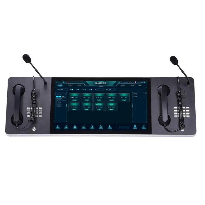
As an important component of IP communication systems, SIP paging speakers are widely used in industrial plants, commercial complexes, campus environments, and similar scenarios. The rationality of their network topology design directly determines call audio quality, paging effectiveness, network stability, and long-term operation and maintenance efficiency. During SIP paging speaker network topology design, engineers often overlook key factors such as network architecture compatibility, bandwidth allocation, and interference resistance. This can result in call stuttering, noise, paging delays, and even device disconnections. Only by mastering scientific topology design methods and optimization techniques, and building a network architecture tailored to specific scenarios, can the communication advantages of SIP paging speakers be fully realized and stable, efficient voice paging transmission be achieved.

1. Core Prerequisites Before SIP Paging Speaker Network Topology Design
SIP paging speaker network topology design should not be a blind network build. It requires a clear understanding of application scenarios, device parameters, and network environments to ensure feasibility and rationality. Unlike standard IP phones, SIP paging speakers must meet both voice communication and audio amplification requirements, placing stricter demands on bandwidth, latency, and stability. Before design, the following three core prerequisites must be clearly confirmed to avoid later rework.
1.1 Clarifying Scenario Requirements and Deployment Scale
Scenario characteristics and the number of devices directly determine the choice of topology structure. Scenario requirements must be carefully analyzed first.
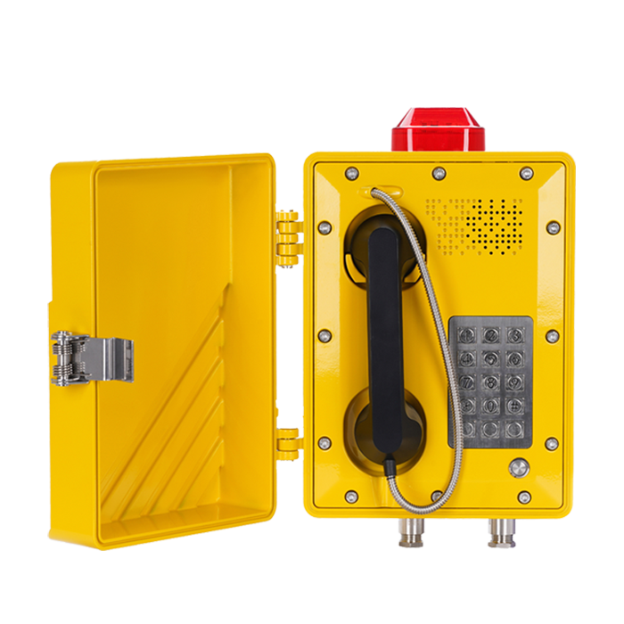
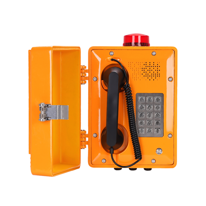
In industrial plants, considerations include workshop distribution, long-distance transmission, and resistance to harsh environments. Certain areas may require explosion-proof SIP paging speakers, and topology design must balance signal coverage and explosion-proof compliance.
In commercial complexes and campuses, devices are relatively concentrated, and attention should be paid to network load capacity under multi-terminal concurrent communication. At the same time, the number of SIP paging speakers, their locations, and whether integration with existing IP telephony or broadcasting systems is required must be clearly defined to prevent misalignment between topology design and actual deployment.
1.2 Confirming Network Environment and Basic Parameters
SIP paging speakers rely on IP networks for voice transmission, and network stability directly affects communication performance. Before design, key network parameters must be thoroughly assessed:
Bandwidth resources: Each SIP paging speaker voice channel requires 8–16 Kbps, while paging audio transmission requires 64–128 Kbps. When multiple terminals operate concurrently, more than 30% bandwidth headroom should be reserved to prevent call stuttering caused by insufficient bandwidth.
Network latency and packet loss: SIP paging systems require network latency ≤100 ms and packet loss ≤1%. Exceeding these limits will result in noise and delays, and the network must be optimized in advance.
Network architecture type: Confirm whether the existing network is LAN, WAN, or hybrid, and whether firewalls, routers, and switches are deployed, ensuring compatibility with the topology design.
1.3 Defining Core Technical Performance Indicators
Based on scenario requirements, define the core technical indicators of the SIP paging speaker topology to guide design decisions:
Voice codec selection: Common codecs such as G.711 and G.729 should be chosen based on available bandwidth. With sufficient bandwidth, G.711 is preferred for better audio quality; when bandwidth is limited, G.729 can be used to save bandwidth.
Paging latency control: In industrial emergency scenarios, paging latency should be controlled within 50 ms to avoid delays in emergency instructions.
Redundancy requirements: For critical scenarios (e.g., industrial emergency systems, campus broadcasting), redundant links must be designed to ensure uninterrupted communication in the event of single-link failure.
2. Common SIP Paging Speaker Network Topologies and Applicable Scenarios
SIP paging speaker network topology must be selected based on deployment scale and scenario characteristics. Different topologies vary in stability, scalability, and maintenance complexity. Engineers should select appropriately to avoid unnecessary operational costs caused by overly complex designs. The following three common topologies are outlined with their characteristics and applicable scenarios.
2.1 Star Topology: Preferred for Small-Scale Deployments
In a star topology, the SIP server acts as the core, with all SIP paging speakers directly connected to the core switch. Communication and paging control are handled via the SIP server. This topology is ideal for small deployments (≤50 terminals).
Key characteristics include simple structure, easy deployment, and low maintenance complexity. Failure of a single terminal does not affect others, allowing rapid fault localization. It also offers good scalability, enabling gradual expansion without major topology changes.
Applicable scenarios include small workshops, office floors, and small campus zones, where terminals are concentrated and concurrency demands are low. However, because the topology heavily depends on the core switch and SIP server, their stability must be ensured, preferably with basic redundancy to prevent total system failure.
2.2 Tree Topology: Suitable for Medium-to-Large Distributed Deployments
The tree topology extends the star topology into a three-layer architecture consisting of core, aggregation, and access layers. SIP servers and core switches form the core layer, aggregation switches manage regional traffic, and access switches connect SIP paging speakers. This topology is suitable for medium-to-large distributed deployments (50–200 terminals).
Its key advantages include hierarchical management and more rational bandwidth allocation. Aggregation layers can control bandwidth usage within regions, preventing localized congestion from affecting the entire network.
This topology is suitable for large industrial plants, large campuses, and commercial complexes. During design, aggregation and access switches should support VLAN segmentation to separate SIP paging speakers from other network devices (such as PCs and surveillance systems). Redundant links between aggregation and core switches are also recommended to enhance reliability.
2.3 Ring Topology: High-Reliability Deployment for Critical Scenarios
In a ring topology, core and aggregation switches are interconnected in a loop, with SIP paging speakers accessing the ring via access switches. The SIP server is located at the core layer. This topology is suitable for highly critical scenarios (≥100 terminals, 24/7 operation required).
Its primary advantage is strong redundancy. If any single link fails, traffic is rerouted through the opposite direction, ensuring uninterrupted communication and paging. Network latency is also consistent, enabling synchronized paging across multiple regions.
Applicable scenarios include large chemical plants, airports, and railway stations. However, ring topologies are complex and costly to deploy and maintain. Switches must support Rapid Spanning Tree Protocol (RSTP) to prevent broadcast storms, and regular inspections of ring link stability are essential.
3. Key Technical Points in SIP Paging Speaker Network Topology Design
Regardless of topology choice, certain technical factors must be addressed during design to ensure stable operation and clear audio quality. The following four key technical points cover the full design lifecycle.

3.1 Bandwidth Planning and QoS Configuration
Stable transmission of voice and paging signals is the core requirement. Bandwidth should be allocated based on demand with sufficient headroom. Each terminal should be calculated at a maximum of 128 Kbps, with an additional 30%–50% reserved for concurrent use.
Quality of Service (QoS) should be configured to assign the highest priority to SIP signaling traffic (ports 5060/5061) and RTP audio streams (ports 10000–20000), ensuring voice traffic is not affected by other network activities such as file transfers or video streaming.
3.2 VLAN Segmentation and Network Isolation
In industrial and commercial environments, various network devices coexist, and their traffic can interfere with voice transmission. SIP paging speakers, SIP servers, and voice gateways should be placed in a dedicated voice VLAN, fully isolated from data VLANs. Inter-VLAN routing should be strictly controlled to improve security and stability.
3.3 Redundancy and Backup Design
For critical scenarios, comprehensive redundancy mechanisms are essential:
Core device redundancy: SIP servers should be deployed in active–standby mode, and core/aggregation switches should use hot standby configurations.
Link redundancy: Dual links with link aggregation should be used between layers to ensure uninterrupted transmission in case of single-link failure.
Power redundancy: UPS systems should be deployed for SIP servers, core switches, and critical terminals to prevent power outages from disrupting emergency communication.
3.4 IP Address Planning and Port Configuration
Static IP addressing should be used for SIP servers, gateways, core switches, and key terminals to avoid communication issues caused by dynamic IP changes. IP segments should be planned by region or device type to simplify maintenance. Unnecessary switch ports should be disabled, and port security should be enabled to prevent unauthorized access to the voice VLAN.
4. Network Topology Optimization Strategies for Common Issues
Even after deployment, issues such as latency, noise, and terminal disconnections may occur. Targeted optimization strategies can address these pain points and further improve system performance.
4.1 Call Latency and Noise
These issues are often caused by insufficient bandwidth, long transmission paths, or interference. Optimization measures include adjusting QoS priorities, reducing topology layers, replacing copper cabling with fiber for long distances, and enhancing EMI protection by using shielded cables and avoiding parallel routing with high-voltage lines.
4.2 Terminal Disconnections and Unstable Communication
Common causes include IP conflicts, loose connections, or improper configuration. Solutions include verifying IP uniqueness, reinforcing physical connections, extending SIP registration intervals, and upgrading firmware on switches and SIP servers.
4.3 Concurrent Call Congestion
In large deployments, excessive topology layers and poor bandwidth allocation can cause congestion. Optimization involves simplifying topology layers, reallocating bandwidth by region, and enabling traffic control to limit excessive usage by individual terminals.
4.4 High Maintenance Complexity
To reduce maintenance difficulty, a unified network monitoring platform should be deployed to monitor device status, bandwidth usage, latency, and packet loss. Comprehensive documentation and standardized labeling of devices can significantly improve troubleshooting efficiency.
5. Common Design Pitfalls and How to Avoid Them
5.1 Overly Complex Topologies
Complex topologies do not always equate to higher stability. Small deployments should prioritize star topologies, medium deployments tree topologies, and ring topologies only for critical scenarios.
5.2 Insufficient Bandwidth Headroom
Always calculate bandwidth using peak demand and reserve 30%–50% additional capacity, combined with QoS configuration.
5.3 Lack of Network Isolation
A dedicated voice VLAN is mandatory to prevent data traffic interference.
5.4 No Redundancy for Core Devices
Critical systems must implement redundancy for servers, switches, links, and power supplies.
6. Topology Acceptance Testing and Ongoing Maintenance
6.1 Acceptance Testing Criteria
Acceptance testing should simulate real-world usage and verify:
Voice quality under single and concurrent calls
Network stability during 72 hours of continuous operation (link failure rate ≤0.5%)
Paging performance and latency (≤50 ms for emergency scenarios)
Redundancy failover performance during simulated failures
6.2 Ongoing Maintenance Practices
Routine inspections, periodic firmware upgrades, and clearly defined emergency response procedures are essential for long-term system reliability.
7. Conclusion
SIP paging speaker network topology design and optimization is a systematic engineering task that balances professionalism, practicality, and reliability. By aligning topology design with scenario requirements, applying key technical principles, avoiding common pitfalls, and implementing rigorous acceptance testing and ongoing maintenance, engineers can ensure stable, high-quality operation. A well-designed and optimized topology not only ensures superior paging quality but also reduces long-term maintenance costs, providing reliable IP communication support for industrial and commercial environments and enabling intelligent system upgrades.
 English
 Deutsch
 한국어
한국어 Русский
 Français
 日本語
日本語 لالعربية
 हिन्दी
 Español
 Português
 繁体中文
繁体中文 简体中文
简体中文